- 1 x N-Channel MOSFET (IRF530N)
- 1 x NodeMCU V3.0
- 2 x Bi-Directional Logic Level Converter (JY-MCU)
- 1 x 12v to 5v Step Down
- 1 x 12V 6amp Power Supply
- 1 x Digital RGB Leds
- 1 x Project Box
- 1 x Power Jacks
- 1 x Toggle Switch
- Header Wires
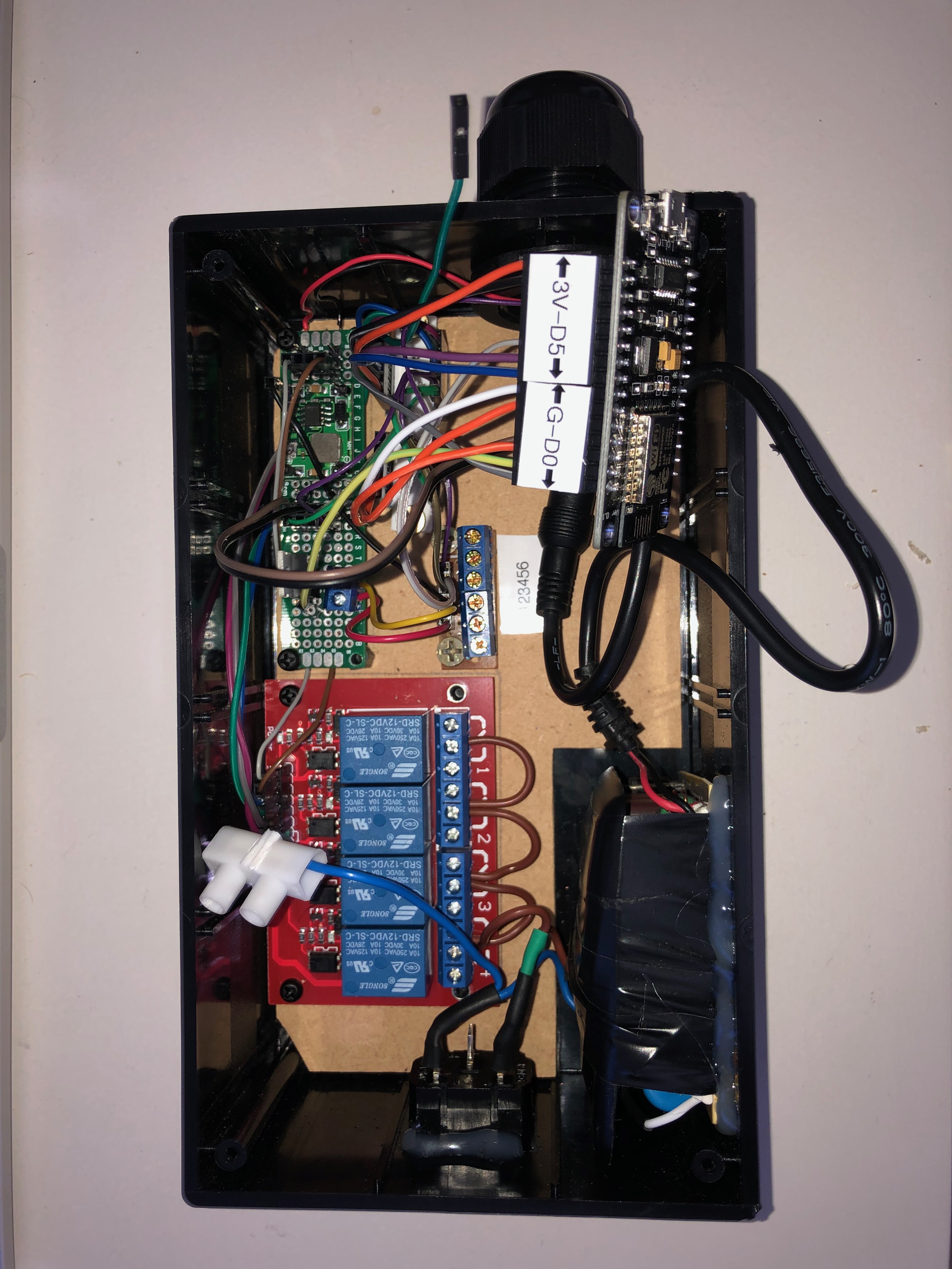
| Wire | Pin | Destination | Destination Pin |
|---|---|---|---|
| Green | VCC | Step down converter 5v | positive |
| Purple | GND | Step down converter 5v | negative |
| Blue | 1* | Relay Module | IN1 |
| Green | 2* | Relay Module | IN2 |
| Brown | 3* | Relay Module | IN3 |
| Purple | 4* | Relay Module | IN4 |
| Wire | Pin | Destination | Destination Pin |
|---|---|---|---|
| Orange | VCC | NodeMCU | 3v |
| Black | GND | NodeMCU | G |
| Blue | 1* | NodeMCU | D6 |
| Purple | 2* | NodeMCU | D5 |
| Gray | 3* | NodeMCU | D0 |
| Green | 4* | - | - |
| Wire | Pin | Destination | Destination Pin |
|---|---|---|---|
| Green | VCC | Step down converter 5v | positive |
| Purple | GND | Step down converter 5v | negative |
| Brown | 1* | Terminal Block | 4 |
| - | 2* | - | - |
| - | 3* | - | - |
| - | 4* | - | - |
| Wire | Pin | Destination | Destination Pin |
|---|---|---|---|
| Orange | VCC | NodeMCU | 3v |
| White | GND | NodeMCU | G |
| Orange | 1* | NodeMCU | D2 |
| - | 2* | - | - |
| - | 3* | - | - |
| - | 4* | - | - |
* numbering starts from next to the GND incrementing from left to right pin as there is no physical numbering on the board
| Pin | Function |
|---|---|
| 1 | White & Color LED VCC (Step down converter 12v positive) |
| 2 | White LED GND |
| 3 | Color LED GND (Step down converter 12v negative) |
| 4 | Color LED Signal |
| 5 | Switch Signal (connected to D7 on NodeMCU) |
| 6 | Switch Ground (connected to G on NodeMCU) |
| Color | Function |
|---|---|
| brown | White & Color LED VCC |
| Black | White LED - GND |
| Green | Color LED - Signal |
| White | Color LED - GND |
| Orange | Switch |
| Blue | Switch |
More photos and other assets available in the assits folder.


